|
Head Part
1 | Front Sub-frame | Big Brakes |
Noland's SERDI 60 machine is part of their success.
It's a machine that puts a three angle cut to your valve seats which exceeds
the factory's original machining, ensuring long life and better valve wear.
|
 |
|
Here the head is attached the the bed of the machine to grind
the valve seats. |
 |
|
Precise measurements with a level are made to ensure the
valve seat is level with the cutting bit. |
 |
|
A test fit of the tool says everything is go for this seat. |
 |
|
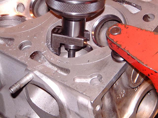
The bit is slowly lowered into place using the valve guide as
vertical alignment. |
 |
|
The special bit begins removing metal for the three angles it
will create. |
 |
|
The bit is raised and the results are inspected. Perfect! |
 |
|
Here is a view of before (on the right) and after (on the
left) - a big difference. |
 |
|
Once completed, vacuum test is performed to ensure a perfect
seal. A valve is placed into the seat that has been cut. |
 |
|
Next, vacuum is applied to attempt to pull air from around
the seat. |
 |
|
Vacuum is applied at high pressure and if the reading looks
like this, you're good. Notice that this new seat is way below the "green"
area for seal. |
 |
|
Intake as well as exhaust are checked for vacuum and the head
is now complete for this step. |
 |
|
Using a TIG welder, more metal is added to the head in order
to build up surface where erosion has removed parts of the water passage. In
this area, 3 spots were welded up. |
 |
|
Next the head is surfaced to ensure it is truly flat. It is
placed on the bed of the surfacing machine. |
 |
|
Again, many measurements are taken before surfacing begins to
ensure it is truly flat. |
 |
|
Mike Noland begins a careful first cut to begin removing the
high areas where the TIG weld was created. This slow first cut ensures that
no chunks of the weld will come out until we hit the full surface of the
head. |
 |
|
The shiny portion shown here shows how these first high
passes are done. |
 |
|
Eventually the full surface is touched by the cutting head. |
 |
|
Now an inspection occurs to see how the surface looks. We
agreed to take a few thousands more off to remove most if not all of the
cutting ring traces in the head. |
 |
|
Finally, it's done with surfacing. The head will be placed
into a pressure washing machine to remove all of the shavings left from the
machining process. |
 |
|
Nice... as Alex Von Falkenhausen had designed it! |
 |
|
A view of the full head. The areas around the water jackets
will be ground to match the other areas now. |
 |
|
Finally assembled, the head is now ready to be attached to
the block when it's completed. |
 |
|
Here you can see very faint traces of the cutting ring but
it's very slight. More material removed and you will probably need higher
octane gas! These lines are so faint they cannot be felt with your finger. |
 |
|
A closeup of the new guide and the valve |
 |
|
Top view shows all parts installed. The rocker shafts
were polished also to ensure smooth wearing again. |
 |
|
Close up of the rocker arms and the shaft. What you can't see
is the new Teflon style seals which will never "puff" like the rubber seals.
BMW figured that one out in the 80s - use the replacement for an M10 318
head. |
 |
|
Front view showing the location of the cam sprocket. All new
springs were also added to each valve. |
 |
|
Another close up view... and she's now all done and bagged up
waiting for the short block to be finished. This was a completely stock
rebuild of the head! |
 |
| |
| Next, in Front Sub-frame
we'll snug up bushings and install the hubs. |

